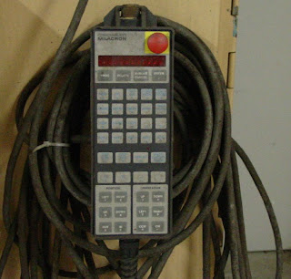
What is a synchro ? Is it related in any way to a stepper motor ? A synchro or "selsyn" is a type of rotary electrical transformer that is used for measuring the angle of a rotating machine such as an antenna platform. In its general physical construction, it is much like an electric motor
.
Synchros play a very important role in the operation of Navy equipment. Synchros are found in just about every weapon system, communication system, underwater detection system, and navigation system used in the Navy. The importance of synchros is sometimes taken lightly because of their low failure rate.
The primary winding of the transformer, fixed to the rotor, is excited by a sinusoidal electric current (AC), which by
electromagnetic induction causes currents to flow in three star-connected secondary windings fixed at 120 degrees to each other on the stator. The relative magnitudes of secondary currents are measured and used to determine the angle of the rotor relative to the stator, or the currents can be used to directly drive a receiver synchro that will rotate in unison with the synchro transmitter. In the latter case, the whole device (in some applications) is also called a
selsyn (a
portmanteau of self and
synchronizing). U.S. Naval terminology used the term "synchro" exclusively (possible exception: steering gear -- info. needed).

With their rugged construction and high reliability, Synchros have been used since World War II as the “angle” transducer of choice for Military, Space and Aviation applications, where only the best will do.
The relation between a synchro and stepper motor is that the stepper motor is just a special type of the synchro. A stepper motor is designed to rotate through a specific angle (called a step) for each electrical pulse received from its control unit.
What are incremental encoders? Are they useful to us in any way?
The incremental encoder, sometimes called a relative encoder, is simpler in design than the absolute encoder. It consists of two tracks and two sensors whose outputs are called channels A and B. As the shaft rotates, pulse trains occur on these channels at a frequency proportional to the shaft speed, and the phase relationship between the signals yields the direction of rotation.
Whenever mechanical rotary motions have to be monitored, the encoder is the most important interface between the mechanics and the control unit.

 What do the poles and zeros contribute to in the control system ?
Poles and Zeros of a transfer function are the frequencies for which the value of the transfer function becomes infinity or zero respectively. The values of the poles and the zeros of a system determine whether the system is stable, and how well the system performs. Control systems, in the most simple sense, can be designed simply by assigning specific values to the poles and zeros of the system.
Physically realizable control systems must have a number of poles greater than or equal to the number of zeros. Systems that satisfy this relationship are called proper. We will elaborate on this below.
Let's say we have a transfer function defined as a ratio of two polynomials:
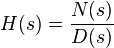
Where N(s) and D(s) are simple polynomials. Zeros are the roots of N(s) (the numerator of the transfer function) obtained by setting N(s) = 0 and solving for s.
Poles are the roots of D(s) (the denominator of the transfer function), obtained by setting D(s) = 0 and solving for s. Because of our restriction above, that a transfer function must not have more zeros then poles, we can state that the polynomial order of D(s) must be greater then or equal to the polynomial order of N(s).
What would the effect of adding a zero to a control system?
Consider the second-order system given by:
G(s) =1 / ((s+p1)(s+p2)) p1 > 0, p2 > 0
The poles are given by s = –p1 and s = –p2 and the simple root locus plot for this system is shown in Figure . When we add a zero at s = –z1 to the controller, the open-loop transfer function will change to:
G1(s) =K(s+z1) / ((s+p1)(s+p2)) , z1>0
 Effect of adding a zero to a second-order system root locus.
We can put the zero at three different positions with respect to the poles:
1. To the right of s = –p1 Figure (b)
2. Between s = –p2 and s = –p1 Figure (c)
3. To the left of s = –p2 Figure (d)
(a) The zero s = –z1 is not present.
For different values of K, the system can have two real poles or a pair of complex conjugate poles. Thus K for the system can be overdamped, critically damped or underdamped.
(b) The zero s = –z1 is located to the right of both poles, s = – p2 and s = –p1.
Here, the system can have only real poles. Hence only one value for K to make the system overdamped exists. Thus the pole–zero configuration is even more restricted than in case (a). Therefore this may not be a good location for our zero,
since the time response will become slower.
(c) The zero s = –z1 is located between s = –p2 and s = –p1.
This case provides a root locus on the real axis. The responses are therefore limited to overdamped responses. It is a slightly better location than (b), since faster responses are possible due to the dominant pole (pole nearest to jω-axis) lying further from the jω-axis than the dominant pole in (b).
(d) The zero s = –z1 is located to the left of s = –p2.
By placing the zero to the left of both poles, the vertical branches of case (a) are bent backward and one end approaches the zero and the other moves to infinity on the real axis. With this configuration, we can now change the damping ratio and the natural frequency . The closed-loop pole locations can lie further to the left than s = –p2, which will provide faster time responses. This structure therefore gives a more flexible configuration for control design. We can see that the resulting closed-loop pole positions are considerably influenced by the position of this zero. Since there is a relationship between the position of closed-loop poles and the system time domain performance, we can therefore modify the behaviour of closed-loop system by introducing appropriate zeros in the controller. [1]
References:
- http://www.palgrave.com/
 Effect of adding a zero to a second-order system root locus.